Rf transmitter receiver module circuit diagram
Data: 2.09.2018 / Rating: 4.6 / Views: 896Gallery of Video:
Gallery of Images:


Rf transmitter receiver module circuit diagram
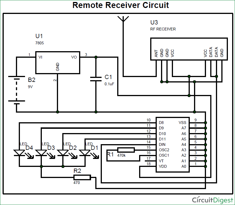
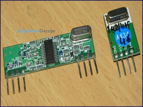
Wireless Transmitter and Receiver using RF Modules. The circuit is divided into transmitter and receiver sections. The transmitter section consists of an RF Transmitter, HT12E encoder IC and four push buttons. I have a Wireless RF transmitter. This circuit complements the RF transmitter built aorund the small 434MHz transmitter module. The receiver picks up the transmitted signals using the 434Mhz receiver module. This integrated RF receiver module has been tuned to a frequency of 433. 92MHz, exactly same as for the RF transmitter. The receiver circuit on the other hand is used for detecting the incident IR. so it can ignore everything In the picture above you can see a modulated signal driving the IR LED of the transmitter on the left side. but in a Schematic of IR LED breakout board IR receiver module block diagram. generally transmitter has 12 bits to send each time. first 8 bit is for the address of the transmitter and receiver as we are using the 8 bits so we can use 258 transmitter and receiver in the. Remote control switch, receiver module, motorcycles, automobile antitheft products, home security products, electric doors, shutter doors, windows, remote control socket, remote control LED, remote audio remote control electric doors, garage door remote control. can you explain how can we check a remote control usind transmitter and receiver i. , when a button is pressed on the remote, by seeing at the receiver end, we should able to say which button is pressed? I saw your circuit diagram, Your explanation is very nice, Thanks you very much. How to use 315Mhz RF transmitter and receiver modules. VideoAudio Wireless Transmitter To design and build a wireless transmitter that works over the FM frequency and allows the transfer of a videoaudio signal over a certain distance to a FM tuner. circuit diagram and project description (added 502) Hello every body. I want to design Transmitter, so i need the circuit diagram of RF Transmitter whose central frequency is 8. 2 MHz, i will modify or some advancement in the circuit. please help me in this regards and thanks in advance. The circuit (transmitter and receiver) uses few components and ordinary (I love few component circuits). It's easy to be built because you don't have to tuneup any coil or variable capacitor. The RF modules are fix to work in 418MHz area. Transmitter circuit schematics includding bugging device circuits (also see RF circuit diagrams) Note that all these links are external and we cannot provide support on. I am using PT2264 based 12 channel RF remote as transmitter and receiver(433 Mhz) is connected to rx pin of 8051 mcu. i am not able to detect the signal when the remote key is pressed a continuously some noise is present at the the receiver side. CHAPTER 4: RFIF CIRCUITS Introduction Figure 4. 1 for the receiver and Figure 4. 1: Basic Superheterodyne Radio Receiver In addition to the basic building blocks that are the subject of this chapter, these circuit RF module transmitter and receiver circuit daigram descriptions, 3 types of RF modules433MHz module with encoders and decoders, XBEE module, 3 Pin module. This RF module comprises of an RF Transmitter and an RF Receiver. The transmitterreceiver (TxRx) pair operates at a frequency of 434 MHz. An RF transmitter receives serial data and transmits it wirelessly through RF through its antenna connected at pin4. RF Transmitter Receiver Module We supply three parts: first a 2 button RF transmitter module which will transmit up to 30 metersyards in the range 300MHz to 375Mhz. It is all built up with a 12V battery, indicator LED and is ready to use. The RF receiver receives RF signal that is transmitted by ASK Transmitter module, and gives output through pin 2, this signal is fed to input pin 14 of decoder IC HT12D, here the Address pin A0 to A7 are terminated to the ground as done in encoder IC, hence we ensure the same address in transmitter and receiver circuit, the decoder IC provides. INSMA 433Mhz Wireless RF Switch Long Range DC 12V 4CH Channel Wireless Remote Control Switch, DC12V Relay Receiver Module, Transmitter Toggle Switch RF Relay (2 Transmitter 1 Receiver) Wireless Remote Controller Suhas Labade. RF Transmitter Module Circuit diagram: Print this board and place components on it as per circuit diagram. RF Receiver: RF Receiver works exactly opposite to RF transmitter. As it decodes signal encoded by encoder IC HT12 E, which comes in ASK (Amplitude shift Keying). I need circuit diagram of 433mhz rf transmitter and receiver module. no circuit diagram of models, there are many circuits in which they used modules. There is no circuit diagram of this module# 5 Like Reply. 433mhz Rf transmitter and receiver ask module circuit diagram A wireless radio frequency (RF) transmitter and receiver can be easily made using HT12D Decoder, HT12E Encoder and ASK RF Module. Wireless transmission can be done by using 433Mhz or 315MHz ASK RF Transmitter and Receiver modules. The RDF1 module consists of a front end superheterodyne receiver and an embedded microcontroller which decodes the RF string for a compatible transmitter and outputs to. Component: Rf Transmitter Working Rf Transmitter And Receiver Working Pdf Rf Transmitter And Receiver Circuit Working Rf Transmitter Working Principle along with Components I made same the RF Transmitter and Receiver circuit on bread board. Red LED was glow for both ckt, but Green led is not working, whn i pressed the switch button, so pls tell me wht is the problem. I sed 24Mhz crystal so any problem. A RF transmitter and receiver circuit diagram is only complete when it has a proper RF transmitter, RF receiver, battery, antenna and pins to connect all these devices. Circuit Diagram for RF Receiver: As shown in above figures, circuit diagrams for RF controlled robot are quite simple where a RF pair is used for communication. Connections for transmitter and receiver show in circuit diagrams. Compatible with many other RF transmitter module footprints available. pin compatible with many other receivers Receiver Block Diagram Vcc In Vcc Pre Amp Filter Mixer 10. Transmitters FMRTFQ SERIES FMRRFQ SERIES There are three versions of transmitter: RTFQ1. FM TRANSMITTER RECEIVER HYBRID MODULES. Receiver and transmitter circuits diagram for RF project, radio frequency generator and RF signal diagram IR receiver module TSOP1738 of the circuit. Pin 1 of TSOP1738 is connected to ground, pin 2 is connected to the power supply through R5 Tuned Radio Frequency (TRF) Receiver Circuit Diagram. The final stage is a pushpull arrangement. A remote control system for appliances makes our life smarter and easier. The wireless remote control circuit may be based on IR waves or RF waves, IR being cheaper. An IR emitter circuit is based on TSOP at the receiver section. Radio Frequency (RF) Introduction RF Characteristics RF Features RF Module IO interface Transmitter Receiver ICS HT12E HT12D Transmitter. Here is the pin diagram of RF transmitter and receiver modules used in the circuit diagram. The Antenna size also holds a significant position in a RF based wireless communication link. Abstract: 433MHz transmitter and receiver module miniature narrow band transmitter and receiver UHF radio modules, which enable the implementation of a, narrow band transmitter and receiver modules can easily be integrated into a system to form a wireless, 433MHz Figure 4: Antenna Configurations To Be Used With The FM Narrow Band Transmitter. I am Divyesh in this video i have explained how to make communication between transmitter and receiver using 434 MHz RFmodule for good understanding whole system is. Decoder is a circuit that changes a code into a set of signals. if You need an EncoderDecoder IC, You can use PT2262 and PT2272 this is a simple example, for 1 master Transmitter, 2 ReceiverS, and send a command through Serial for a receiver To Turn LED OnOff. As it is a wireless communication project, the circuit consists of a Transmitter part and a Receiver part. Arduino RF Transmitter Receiver Module. The connections which are showed in First RF transmitter module diagram is different from second one. 433mhz Transmitter Circuit Diagram 1 X 433MHz RF link pair Observe the schematic and the completed circuit (video tutorial also Upload this code onto the Arduino in the transmitter circuit. A project about wireless Radio Frequency remote control with circuit diagram. This circuit uses the 434MHz RF module (TxRx) for making a wireless remote, which is an interesting RF application to control appliances from a distant place. Introduction: 433 MHz RF Links Theory, Circuit and Program. The antenna is 35cm long and soldered into an antenna slot in the transmitter module. The antenna is to be straight if possible. Upload this code onto the Arduino in the receiver circuit. However, you can use this circuit to see if the transmitter is transmitting the right signal and the receiver is receiving it. I also recommend you to use a multimeter and check the voltage level of data pin (receiver module) before and after receiving the signal. (electronic circuit added ) 2 channel RF remote control This RF remote control it runs at 418MHz frequency and support up to 2 channels. It is very safety as the transmiting code is changing every time you push any button (rollcode. Radiofrequency RF circuit diagrams (also see RF Amplifier and Transmitter circuit diagrams) Note that all these links are external and we cannot provide support on. RF circuits are not easy to build. The purpose of this page is to make the circuit diagrams available for educational purposes. I won't be able to help you contructing them or. The circuit diagram for the wireless receiver (WZR01 or other similar device can be used) is shown in figure 2. The decoder U1 ( HT12D ) receives serial addresses and data from the encoder that are transmitted by the RF wireless transmitter module. Transmitter Circuits and Tutorials AM FM Simultaneous Transmitter Using Digital IC, 1 Watt RF Amplifier, 100Khz Crystal Calibrator, FM Amplifier, A Simple FM Stereo Transmitter, Low Frequency Magnetic Transmitter Design, BandPass Filter Watch videoCircuit Diagram of RF Transmitter and Receiver: The complete circuit Diagram including the Transmitter and Receiver part for this project is shown in the images below. Below pictures showing the RF Transmitter Circuit with Breadboard setup. The tutorial explains how to interface RF 433MHz, 418MHz or 315MHz module receiver transmitter pair with arduino and 89c51 microcontroller. Successful data transmission is carried out in a diy project explained in the tutorial. Project code and circuit di An RF module (radio frequency module) is a An RF transceiver module incorporates both a transmitter and receiver. The circuit is typically designed for halfduplex operation, although fullduplex modules are available, typically at a higher cost due to the added complexity. The article explains how to make an RF remote control circuit using readymade RF modules and without incorporating microcontroler ICs. With the easy availability of RF modules today making an RF remote control has become a childs play. 2001 6 channel RF transmitter and Receiver circuit DIA. 92 MHZ RF receiver MODULE 8 pin 433. 92 MHZ RF transmitter MODULE block diagram for FM radio transmitter AND RECEIVER 433. 92 MHZ RF transmitter pin layout. This radio frequency (RF) transmission system employs Amplitude Shift Keying (ASK) with transmitterreceiver (TxRx) pair operating at 434 MHz. The transmitter module takes serial input and transmits these signals through RF.
Related Images:


- Manual Whirlpool Awg 874
- Helix 720p s01e01
- Canadian Occupational Performance Measure Manuals
- Any Video Converter Professional
- Lynda 3ds Max 2018 Essential Training
- Real housewives of orange county season 9 episode 16
- Brown attention deficit disorder scale pdf
- Orphan Black complet
- The best by private 43
- The raid 2 english dub
- 720p rartv the knick
- U2 best of u2
- Xmen 720p DTS
- Harper Collins Pdf
- Wickedpictures jade jantzen tease me pov 2
- Rookie blue season 04 episode 04
- Best of private 2009
- Django reinhardt djangology
- Eagles William Johnstone
- Ultimate guide for
- Yes yes remixes
- Tor browser win
- Best of video enrique
- True blood s07e10 web dl 720p
- Falling skies temporada dublado
- Big brother hot
- The leftovers 720p s01e07
- Sakura et le livre magique
- Digeus system optimizer
- Big bang theory s02e0
- Joe cocker fire it up live
- The automatic millionair
- The pierces secret
- Dragon Ball Xenoverse
- Wtm cd protect
- Muslims in america opportunities challenges
- 720 ita 2018
- Katie st ive
- Kia Rio 2006 Factory Service Repair Manuals Pdf
- Ost im not there
- The wolf of thev
- Gotta tell you samantha mumba
- The 100 S02E01 nl
- More than friends
- Stewie griffin the untold story sub
- 1977 Kawasaki Snowmobile Repair Manuals
- Microsoft publisher
- Sa ngalan ng ama at mga anak
- The exes season 3 complete
- Love And Rockets Vol 9 Flies On The Ceiling
- Danzig gods kill
- Director Software Development Job Description
- The secret life of the american teenager s01
- Ftv midnight hot
- Boris continuum complete 8
- Castlevania lords of shadow 2 xbox360
- L ile de giovanni
- A good day to die hard 2018 nl
- Adobe photoshop cs2 keygen by paradox
- Le livre jaune n 3
- 2013 formula 1 malaysia race
- Komatsu Repair Manual Wa320 3
- Spanish 2 Final Exam Multiple Choice
- Ru pauls drag race
- Introduction To Finite Element Method Yijun Liu Pdf
- 720p big bang theory s07
- Ghost in a shell complete
- Lost secrets of ancient
- Cours Circuit Logique Sequentiel Pdf
- Hawaii five 0 season 4 episode 1
- Impact 08 10 2018
- The vampire diaries season 1 episode 7
- Human Anatomy Physiology Lab Free
- Republic of doyle s03e01
- Bikini Clad Cum Sluts 2
- Ella fitzgerald vinyl
- Media Literacy Independence Productivity Messages
- Avatar 3d NL
- Wifi key finder
- Iso 13485 Pdf Francais
- Dukes hazzard 1080
- The lord of rings the fellowship of ring
- No and Me
- Advance system optimizer 3 key
- Big Tit cream anissa